
Operation of IP Data Networks
Recognize the purpose and functions of various network devices such as Routers, Switches, Bridges and Hubs.
Repeaters
Repeaters are Layer 1 devices utilizing the Physical Layer and are considered as outdated technology today. They have been replaced by Hubs and Switches. But for the purposes of understanding; a repeater consists of a transmitter and a receiver. The function of a repeater is to receive the signal, amplify it and retransmit it enabling the signal to be transmitted over a longer distance.
Repeaters are essential to maintain the quality of signals as they degrade over a distance. Repeaters regenerate and retime the signal, helping it travel a longer distance. Repeaters may be single port or multi port. The figure given below illustrates a repeater.

A Multiple Port Repeater is termed as a Hub. It is also a Layer 1 device utilizing the Physical Layer. It can comprise of ports varying from 2 to 24 in number and may also be known as a workgroup hub. Its main job is cleaning up signals. By isolating the end points, Hubs increase the network reliability. A hub retransmits data on all the other ports. A twisted pair cable is used for achieving physical connectivity. The figure given below illustrates a HUB

Hubs can be of two types; Active and Passive hubs. The difference between the two is that Active Hubs regenerate the incoming signal, whereas the Passive Hubs do not do so. Active Hubs need individual power supply to help with the gain of signal before the data is forwarded to all ports. Gain is an electrical term, representing the ratio of signal output to signal input of a system.
The advantage of Hubs is that they are inexpensive. If more efficient use of bandwidth and its distribution among the ports is required, hubs may not be the best option. Traffic congestion because of collisions on the network is indispensable while using hubs. The best solution in this case is to use a switch.
Network Interfaces:
Network interfaces provide connectivity between an end-user computer to the public network. Depending on the interface that is being used, up to three light-emitting diodes (LEDs) may appear. These diodes help to determine the status of the connection.
- The Link Light LED: It lights up when the connectivity is there;
- The Activity Light LED: It flickers if some activity is taking place on the line;
- The Speed Light LED: This light indicates the connection speed. It may be there on the interface, it may not be there.
Blinking lights and colors other than green are indicative of error conditions.
Bridges:
Bridges were used as a solution for issues relating to network congestion. Hubs and Repeaters were longer proving sufficient to meet the challenges provided by systems growing complex. In comparison to Repeaters and Hubs and Bridges used the concept of segmentation. Repeaters and Hubs which do not use segmentation, share the same bandwidth and hence the traffic congestion on a network. When the other device on the network is not aware of the existence of a Bridge, it is called a Transparent Bridge. Figure 3 given below illustrates a Bridge.

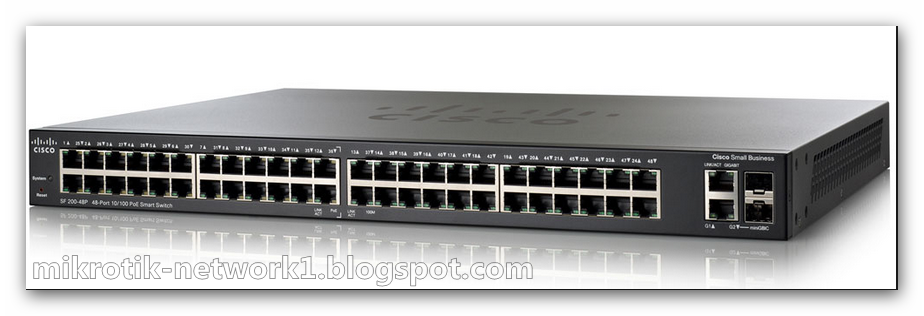
Switches are very smart Bridges with the characteristics of being multi port and high speed. The differ bridges from the point that bridges process frames in software whereas switches process frames in hardware. Switches do so by using application integrated circuits (ASIC’s). Figure 4 given below illustrates a Switch.

- Speed Back Plane: this function increases the speed of the network; it allows monitoring of multiple conversations.
- Data Buffering: This function allows storage of frames and later forwarding the frame to the right port.
- High Port Density: Switches can support multiple ports at one time.
- High Port Speed: Switches can support high speeds varying from speeds from 10 Mbps to 10Gbps.
- Lower Latency: Latency is a term that is used to measure the time it takes an incoming frame to come back out of a switch. In the case of switches latency is low.
- VLAN’s: This feature allows segmentation of networks into separate broadcast domains.
These features permit micro segmentation.
Micro segmentation:
Micro segmentation means that a dedicated switch ports are created for every end station; meaning that dedicated paths for sending and receiving transmission with each connected hosts are created. These reduce traffic congestion to a great extent for the reason that separate collision domain and individual bandwidth is available for every host. But faster computers, broadcasts and multicasts can still cause congestion.
Bridges and Switches perform the following tasks:
- Ascertainment of MAC Address: Examine the source MAC address of every inbound frame to ascertain its MAC address;
- Filtration/Forwarding: Depending on the destination of the MAC address, filtration or forwarding of frames as the case may demand;
- Elimination: Eliminating loops caused by superfluous connections.
Icon standard network

Ccna Certified Mr.Mohamed Samir


0 comments:
Post a Comment