Network Services

Hotspot Mikrotik 777

Technology has been used Bootstrap Compatible Mobile.

Design Hotspot-12 beautiful Server Mikrotik

Design Hot Spot Mikrotik Free

Hotspot login server free

Hotspot login server free.

Merge 2 lines in server Pfsense?

Merge 2 lines in server Pfsense server free.

setup squid cahce in Ubuntu

How to setup squid cahce in Ubuntu ?

Friday, May 18, 2012

ISA 2006 Array

Quoting Microsoft 

ISA 2006 Array, Step by step configuration guide

ISA 2006 Array

Step by step configuration guide


Index
Preface. 


Step 1, Install Configuration Storage Server.


Step 2, Create an array.


Step 3, Install your ISA servers .


Step 4, Configure network objects .


Step 5, Finishing up and some notes .


Preface
This guide will guide you step by step in order to deploy an ISA 2006 array in AD
environment. It does not cover server publishing in any way. It just covers CSS, NLB
and VIP configuration to get the array up and running.
This guide will be based on a setup of five computers in a lab environment configured
as the exhibit below:

All of the computers are running Windows 2003 w. SP1
The environment consists of two network segments like:


Network A


IP: 10.42.43.0
Mask: 255.255.255.0
Router: 10.42.43.254


Network B


IP: 192.168.15.0
Mask: 255.255.255.0
Router: 192.168.15.254


Step 1, Install Configuration Storage Server


First we need to ensure that we have the CSS (Configuration Storage Server)
installed. This server will hold the configuration for the enterprise and this is where
the ISA servers will get their firewall configuration from.
The Configuration Storage server uses Active Directory Application Mode (ADAM) for
storage. When you install the CSS, you also automatically install ADAM on the
server.
The CSS may be one of the ISA servers, but my recommendation is to place this on
a separate server on the inside, in our case Network B. You may also install an
alternative CSS later on to be used as backup if the first CSS fails.
The communication between CSS and the ISA servers are done through MS Firewall
Storage protocol, which is based on LDAP, outbound TCP protocol on port 2171.

Choose to install Configuration Storage Server on your separate windows 2003
server or one of your ISA servers. Click Next


Next would be to configure a new ISA server enterprise for our new array to exist in.
Click Next


We´ll deploy this in an already configured AD environment, but we could also have
chosen to deploy within workgroups or domains without trusts.
In the later case we would use certificates between the ISA servers and the CSS.
This, however, will require a CA server.


Click Next to finish up here


Step 2, Create an array
Let the installation progress now and when it´s ready open up the ISA Server
Management MMC and navigate to Array, rightclick and select New array


Type in the name for your new array and click Next

Type in the DNS name of the array to be used by Firewall Clients and click Next


Accept Default Policy and click Next


Specify what kind of firewall rules that will be available to this array and click Next


Let the installation progress now and when it´s ready open up the ISA Server
Management MMC


Navigate to Firewall Policy

Add the ISA servers that belong to your array into the Managed ISA Server
Computers in the Network Objects tab under Toolbox


Apply the changes.


Step 3, Install your ISA servers
This step must be repeated for each of your ISA servers that will be working in the
array


This time we´ll choose to install just the ISA server services. Click Next


Enter the FQDN of the CSS or just browse the directory. Click Next

Let the installation progress now and when it´s ready open up the ISA Server
Management MMC

If you got this error you probably forgot to add the ISA servers that belong to your
array into the Managed ISA Server Computers in the Network Objects tab under
Toolbox as seen in Step 3


Now the ISA server must join the array we created earlier. Click Next


Choose the array. In our example the name of the array is Skynet

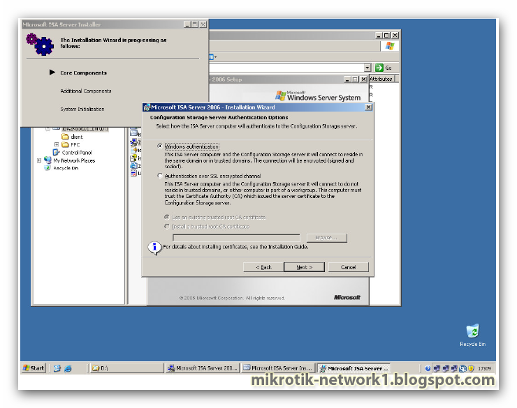
Since the ISA server and the CSS belong to the same AD we´ll use Windows
authentication


Accept probed value is it´s correct or specifiy the IP range of the Internal interface
Let the installation progress now and when it´s ready open up the ISA Server
Management MMC


Step 4, Configure network objects
Now NLB (Network Load Balancing) and VIP (Virtual IP) must be configured.


Navigate to Enterprise Networks

Edit the Internal properties. Add the internal IP range. Click OK
Navigate to Networks under your array configuration

Click Add Network and select the Internal object. Click OK
Click Add Adapter and select the Internal interfaces for ALL your ISA servers
belonging to the array. Click OK all the way back to MMC main window.
Choose Enable Load Balancing Integration from the Tasks tab in the right section of
MMC and a wizard will start


Now enter the VIP (Virtual IP) for each Interface and click Next to finish the wizard.


Step 5, Finishing up and some notes

Just a note regarding CARP here. I´ve myself encountered problems when
configuring systems like payment aso. These systems can be quite sensitive to
changes in the client session, especially if the session all of a sudden changes IP.
These sessions must then be configured as so called Sticky Sessions that will remain
the same as long as communication is established.
If you have this problem then disable CARP.


Now look at your Server status. If everything is OK you should have small green
icons indicating that there are not problems. If you see small timers instead it´s just
because the CSS have not yet retrieved status information from your ISA servers.
To test the configuration using ICMP (ping) you might have to make some temporary
changes to the System Policy as seen below


Now you should be able to do a ping from a host on Network B to a host on Network
A and kill one of the ISA servers. All you should notice is a few Request time out
before the surviving firewall takes over.


RouterBOARD 750G

Quoting the official website Mikrotik

Quick Setup Guide and Warranty Information


First use

       1. Connect your WAN cable to port 1, and LAN computers to ports 2-5
       2. Set LAN computer IP configuration to automatic (DHCP)
       3. RB750G Default IP address from LAN is 192.168.88.1 or http://router


Powering

The board accepts powering from the power jack or from the first ethernet port (Passive PoE):
       ● direct-input power jack (5.5mm outside and 2mm inside diameter, female, pin positive plug) accepts              .           8..28V DC
       ● first ethernet port accepts passive Power over Ethernet accepts 8-28V DC
Normally the power consumption of this device is 2.4W, under maximum load - 3.6W

Booting process

This device doesn't come fitted with a Serial Port connector, so initial connection has to be done via the Ethernet cable, using
the MikroTik Winbox utility. Winbox should be used to connect to the default IP address of 192.168.88.1 with the username
admin and no password.


In case IP connection is not available, Winbox can also be used to connect to the MAC address of the device. More
information here:

      http://wiki.mikrotik.com/wiki/First_time_startup


In case you wish to boot the device from network, for example to use MikroTik Netinstall, hold the RESET button of the
device when starting it until the LED light turns off, and RB750G will start to look for Netinstall servers.
By default, the device is preconfigured with a simple firewall on the WAN port, this configuration can be viewed when first
connecting to the Router via Winbox. It will ask whether to keep this configuration or clean it to use your own.


Extension Slots and Ports
● Five individual Gigabit Ethernet ports, supporting automatic cross/straight cable correction (Auto MDI/X), so you can
use either straight or cross-over cables for connecting to other network devices. The First Ethernet port accepts 8..28
V DC powering from a passive PoE injector.

Buttons and Jumpers
       ● ROS reset jumper hole (on the bottom of case, behind one of the rubber feet) – resets RouterOS .    .         software to
         defaults. Must short circuit the metallic sides of the hole (with a screwdriver, for example) and boot the  .        device. Hold
         screwdriver in place until RouterOS configuration is cleared.
       ● RouterBOOT reset button (RESET, front panel) has two functions:
       ● Hold this button during boot time until LED light starts flashing,
         release the button to reset RouterOS configuration (same result as with reset hole)
       ● Hold this button during boot time longer, until LED turns off,
         then release it to make RB750G look for Netinstall servers.


Operating System Support
Currently tested operating system is MikroTik RouterOS (starting from version v4).

Copyright and Warranty Information
Copyright and Trademarks. Copyright MikroTikls SIA. This manual contains information protected by copyright law. No
part of it may be reproduced or transmitted in any form without prior written permission from the copyright holder.
RouterBOARD, RouterOS, RouterBOOT and MikroTik are trademarks of MikroTikls SIA. All trademarks and registered
trademarks appearing in this manual are the property of their respective holders.
Hardware. MikroTikls SIA warrants all RouterBOARD series equipment for the term of one year from the shipping date to be
free of defects in materials and workmanship under normal use and service, except in case of damage caused by
mechanical, electrical or other accidental or intended damages caused by improper use or due to wind, rain, fire or other
acts of nature.
If you have purchased your product from a MikroTik Reseller, please contact the Reseller company regarding all warranty
and repair issues, the following instructions apply ONLY if you purchased your equipment directly from MikroTik Latvia
To return failed unit or units to MikroTikls you must perform the following RMA (Return Material Authorization) procedure.
Follow the instructions below to save time, efforts, avoid costs, and improve the speed of the RMA process. Take into
account that all goods have one year warranty.
Instructions are located on our webpage here: http://rma.mikrotik.com
Manual. This manual is provided “as is” without a warranty of any kind, expressed or implied, including, but not limited to,
the implied warranty of merchantability and fitness for a particular purpose. The manufacturer has made every effort to
ensure the accuracy of the contents of this manual, however, it is possible that it may contain technical inaccuracies,
typographical or other errors. No liability is assumed for any inaccuracy found in this publication, nor for direct or indirect,
incidental, consequential or other damages that may result from such an inaccuracy, including, but not limited to, loss of
data or profits. Please report any inaccuracies found to support@mikrotik.com