Network Services

Hotspot Mikrotik 777

Technology has been used Bootstrap Compatible Mobile.

Design Hotspot-12 beautiful Server Mikrotik

Design Hot Spot Mikrotik Free

Hotspot login server free

Hotspot login server free.

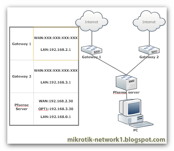
Merge 2 lines in server Pfsense?

Merge 2 lines in server Pfsense server free.

setup squid cahce in Ubuntu

How to setup squid cahce in Ubuntu ?

Friday, May 23, 2014

Configuring a Windows 9x Network


Configuring a Windows 9x Network
The configuration of a Windows 9x network centers on the Control Panel’s Network program. From this one interface, you can configure client software, protocols, NICs, and the network
services you want this machine to perform. To access the Network program, select Start Settings  Control Panel and double-click Network in the Control Panel window that appears.
Windows 9x will display the Network window. The Network window has three areas of interest: the Components list, the Primary Logon list, and the File and Printer Sharing button.

NOTE:
If you already have some networking components installed, you can simply right-click the Network Neighborhood icon on your Desktop and choose Properties from the pop-up menu.

Networking Components
First, let’s review the four basic types of networking components that can be added in the Network panel, as shown in Figure 6.10. This screen can be reached by clicking Add on the Configuration
tab. 


FIGURE 6 . 1 0 The Select Network Component Type window


The networking components are as follows:
Client As mentioned before, the client is software that allows your machine to talk to servers on the network. Each server vendor uses a different way of designing its network access. Therefore,
if a computer needs to get to both a Novell and a Microsoft network, the computer must have two pieces of client software installed, one for each type of server. The three network client
groups supported by Windows 9x are for Microsoft, Novell, and Banyan servers.

NOTE:
UNIX/Linux clients are also supported natively, but they use their own set of tools (e.g., Ping, nslookup, etc.) and don’t require the installation of a client piece in this area.
Adapter The adapter is, technically, the peripheral hardware that installs into your computer, but in this case, it refers to the software that defines how the computer talks to that hardware.
If you do not have the proper adapter software installed, your PC will not be able to talk properly to the NIC, and you will not be able to access the network until you change the adapter to
one that is compatible with the hardware. It is often best to think of an adapter as simply a network driver, which is what it really is. Many adapters are supported by Windows 95, and Windows
98 and the more recent versions support even more, with support for more recent hardware. Adapter drivers can also be downloaded from most NIC vendors’ websites.

Protocol Once the client service and the adapter are installed, you have cleared a path for communication from your machine to network servers. The protocol is the computer language that
you use to facilitate communication between the machines. If you want to talk to other people, you have to speak their language. Computers are no different. Among the languages available
to Windows 9x are NetBEUI, NWLink (IPX/SPX), and TCP/IP.

Service A service is a component that gives a bit back to the network that gives it so much. Services add functionality to the network by providing resources or doing tasks for other computers.

In Windows 9x, services include file and printer sharing for Microsoft or Novell networks.

Installing Components
Let’s suppose you want to connect to Microsoft servers on your network (including Windows XP, 2000 Server, 2000 Professional, Windows NT, or Windows 9x with sharing enabled). To connect to this network, you must have at least the following three components (services, the fourth component, are not required at this point):


  • A client, such as Client for Microsoft Networks
  • A protocol (whichever protocol is in use on the network; generally TCP/IP)
  •   An adapter (whatever is in the PC)


To install a client and protocol for use with your network adapter, follow these steps:

1.Click the Add button toward the bottom of the Network window. This will display the screen shown previously in Figure 6.10.

2. In this screen you can choose what type of item you are going to install. In this example, you’re installing the Client for Microsoft Networks, so click Client and then click Add.

3. You will see a screen similar to the one in Figure 6.11. This screen is the standard “pick your component” screen that Windows 9x uses. On the left, select the company whose software
(or driver) you want to install (in this example, Microsoft). When you have selecteda manufacturer, a list of the software that Windows 9x can install from that company
appears on the right.

4. Click Client for Microsoft Networks when it appears in the right pane, and then click OK. Windows 9x will bring you back to the Configuration tab of the Network program.

5. Once you have a client installed, you can verify that the protocol you need is present. TCP/IP generally installs by default, but this is not always so. If it is not present, click Add on the Configuration
tab. In the Select Network Component Type window, select Microsoft in the Manufacturers list and TCP/IP in the Network Protocols list. Click OK to complete the installation.

NOTE:
When it is first installed, TCP/IP is configured to expect that a special server, called a Dynamic Host Configuration Protocol (DHCP) server, is available on the network to provide it with information about the network. If a DHCP server is not available, the protocol will not function properly. Consult your administrator to see whether the network uses DHCP or static addressing. In static addressing, all TCP/IP settings must be manually added, and in this case, you  will need additional information from the administrator.

The list of components should reflect your additions and show which network components are currently installed on this machine. If there are a number of components, a scroll bar appears on the right side of the screen. The scroll bar allows you to see all of the clients, network adapters, protocols, and services that might be installed. Once the client and protocol are installed, you will have all the software you need to connect to the network. At this point, just a few choices remain. Don’t close that Network program yet!

FIGURE 6 . 1 1 Selecting the software you want to install


Determining Your Primary Logon
A Windows 9x workstation can support multiple simultaneous network types. For example, a user can log in to both Novell and Microsoft networks, assuming that both network clients are
installed and configured correctly. The Primary Network Logon drop-down list determines which network type you will log on to first. If you have not yet installed a network client, this
list will only give you one option: Windows Logon.
We have already installed a Microsoft network client, so select the Client for Microsoft Networks as the primary logon, as displayed in Figure 6.12. Once you have made this selection, click OK. The Network program will close, and you will be asked to restart the computer so that the new settings can take effect. (You may also be asked for the location of any files that Windows can’t find, so you may have to insert your Windows CD.) Until you reboot, the network will not function. When the machine restarts, the network
should be available.

FIGURE 6 . 1 2 Choosing a primary network logon

Configuring a Windows 2000 Network Client
For the most part, the concepts behind configuring Windows 9x are the same as the concepts for configuring in Windows 2000. You still need a client, a protocol, and an adapter, for instance, but the difference is in how they are configured. First, the Network program is now called Network and Dial-up Connections and is organized differently. When you first access the Network and Dial-up Connections window, you will see that, instead of a list of all components, you are greeted simply by a Make New Connection
icon and a Local Area Connection icon, as shown in Figure 6.13.

NOTE:
If you do not see a local area connection, your NIC or your modem is either not present or not functioning properly. If you see more than one LAN connection, it means that you have multiple NICs installed. (Windows 2000 Server, for example, can support multiple NICs.)
To add client software and protocols, right-click the LAN connection and select Properties. You should find that everything you need is in place because the client and IP are installed by
default on the LAN adapter.

FIGURE 6 . 1 3 The Network and Dial-up Connections window

NOTE:
File and Printer Sharing for Microsoft Networks is also installed by default. To disable it, clear the check mark next to the service. To remove it completely, click Uninstall.

You can also add additional clients, protocols, and services. Windows 2000 supports the same components that Windows 9x supports, plus some additions. (The only component not
supported in 2000 that is in 9x is the Banyan client.) Once you have verified that the Client for Microsoft Networks and TPC/IP are installed, click OK. You should not have to reboot after
making changes to the network settings in Windows 2000.

Thursday, May 22, 2014

Workstation Configuration "Network + Chapter 6"


Workstation Configuration
In addition to knowing how to configure a station’s hardware, you must be able to configure a Windows workstation to connect to the different types of network operating systems (NOSes)
that might be on your network. For the Network+ exam, you should be able to configure these workstations to connect to the following operating systems:

  • Windows NT/2000 servers
  • NetWare
  • UNIX/Linux
  • Macintosh

The process for configuring Windows to connect to these various operating systems is basically the same for all server OSes (only the workstation software component differs very slightly), so
we’ll just cover the two most popular client operating systems’ network configurations.

Wednesday, May 21, 2014

Installation Type "wireless network"


Installation Type
Let’s say you just bought a wireless NIC for your laptop and a WAP. What can you do with them? Well, that all depends on the type of installation you are going to do with these devices.
There are two major installation types: ad-hoc and infrastructure mode. Each 802.11 wireless network device is capable of being installed in one of these two modes.
Ad-Hoc Mode
The simplest installation type for wireless 802.11 devices is ad-hoc mode. In this mode, the wireless NICs (or other devices) can communicate directly without the need for a WAP. A good
example of this is two laptops with wireless NICs installed. If both cards were set up for ad-hoc mode, they could connect and transfer files (assuming the other network settings, such as protocols,
were set up correctly).
To set up a basic ad-hoc wireless network, all you need are two wireless NICs and two computers. Install the cards into the computers according to the manufacturer’s directions. During
the installation of the software, you will be asked at some point if you want to set up the NIC in ad-hoc mode or infrastructure mode. For an ad-hoc network, choose the ad-hoc mode setting.
Then bring the computers within range (90–100m) of each other.The computers will “see” each other and you will be able to connect to each other.

NOTE:
In order to transfer files, both computers will need to have security settings that will allow it.

Figure 6.6 shows an example of an ad-hoc wireless network. Note the absence of an access point.


FIGURE 6 . 6 A wireless network in ad-hoc mode

Infrastructure Mode
The most common use for wireless networking equipment is to provide the wireless equivalent of a wired network. To do this, all 802.11 wireless equipment has the ability to operate in what
is known as infrastructure mode. In this mode, NICs will only communicate with an access point (instead of each other as in ad-hoc mode). The access point will facilitate communication
between the wireless nodes as well as communication with a wired network (if present). In this mode, wireless clients appear to the rest of the network as standard, wired nodes. Figure 6.7 shows a typical infrastructure mode wireless network. Note the access point and

that it is connected to the wired network.


FIGURE 6 . 7 A wireless network in infrastructure mode


When configuring a client for wireless infrastructure mode, you need to understand a couple of basic wireless concepts: SSID and security. The SSID (short for Security Set Identifier) is the
unique 32-character identifier that represents a particular wireless network. All devices participating in a particular wireless network must be configured with the same SSID. If a wireless network
is to have more than one access point that provides access to the same wireless network, the access points must all have the exact same SSID.

NOTE:
Multiple access points with the same SSID spread over a large area allow a user to move around that area while maintaining a connection to the wireless network. This process is called roaming.
Because most access points are configured by default to broadcast their SSID so wireless clients can browse and find them, and because wireless signals can travel long distances (even outside
of a building), security is extremely important on wireless LANs. To that end, most access points have one or more of the following security measures in place: WEP Short for Wired Equivalent Privacy, this protocol, when enabled, requires that both
access point and workstation are configured with the same 64-bit, 128-bit, 152-bit, or 256-bit encryption key in order to communicate. This key is manually configured by the network
administrator and usually comprises a string of alphanumeric or hexadecimal characters.

NOTE:
You may also see WEP referred to as the Wired Equivalency Protocol, although that is not the original term for which the acronym was used.
MAC List Some WAPs are capable of restricting which clients can connect to the AP by keeping track of authorized MAC addresses. The administrator configures the AP with the list of all
the MAC addresses of wireless NICs that are authorized to connect to that AP. If a NIC with a MAC address not on the AP’s MAC list tries to connect, it will be rejected. Disabling SSID Broadcast By default, WAPs broadcast their SSID to make it easier for clients
to find them. For example, Windows XP has a built-in utility that allows users to browse for WAPs. However, you can turn this feature off. You then must configure each client with the
SSID of the WAP that client will connect to.

Real World Scenario 
War Driving
Wireless networks are everywhere these days. Electronics retailers are selling wireless access points for less than $100 and they are flying off the shelves. You can find WAPs in public places
like shopping malls, coffee shops, airports, and hotels. In some cities, you can walk in a downtown area and find WAPs in almost every business. This proliferation of WAPs has led to a new hobby for the technologically savvy with time on their hands: war driving. This is the practice of driving around in a car with a laptop, a wireless NIC, and a high gain antenna to locate open WAPs (especially those with high-speed Internet access). There are various software programs that make this process easier (some even have Global Positioning System (GPS) interface software to make relocating the open access point again even easier). War drivers can be a threat because they can potentially access anything on
your wireless LAN (and anything it’s attached to). In addition, they are potentially consuming resources on your network. But, the threat is low in most cases. If you notice slow-moving vehicles
outside your home or business (especially those with computer equipment inside), you might be the target of a war driver.

TIP:
These features by themselves aren’t completely secure, but using multiple wireless security features together will make a wireless LAN much more secure.

Signal Degradation
Another factor to consider when installing a wireless network is signal degradation. Because the 802.11 wireless protocols use radio frequencies, the signal strength varies according to many
factors. The weaker the signal, the less reliable the network connection will be, and thus the less usable as well. These factors are included in the following list:
Distance This one should be fairly obvious. The farther away from the WAP you get, the weaker the signal. Most APs have a very limited maximum range (less than 100m for most systems).
To some degree, this can be extended using amplifiers or repeaters or using different antennas. Walls The more walls a wireless signal has to pass through, the more attenuated (reduced) the
signal becomes. Also, the thicker the wall, the more it interrupts the signal. In an indoor office area with lots of walls, the range of wireless could be a low as 25m. Protocols Used Another factor that determines the range of wireless LAN is the protocol used.
The various wireless 802.11 protocols have different maximum ranges. As discussed earlier in Table 6.2, you can see that the maximum effective range varies with the 802.11 protocol used.
Interference The final factor that affects wireless performance is outside interference. Since 802.11 wireless protocols operate in the 900 MHz, 2.4GHz, 5GHz range, interference can come from several sources, including other wireless devices, such as Bluetooth, cordless telephones, microwave ovens (a huge adversary of 802.11b and 802.11g), cell phones, other wireless
LANs, and any other device that transmits radio frequency (RF) near the frequency bands that the 802.11 protocols use.

 Hardware Installation
The installation of 802.11 equipment is fairly simple. There are really two main types of components
in 802.11 networks: WAPs and NICs. Wireless NIC installation is just like installing any other network card (which you will learn later in this chapter). But, once it’s installed, you must connect to a WAP. WAP installation is fairly simple as well. Take it out of the box, connect the antenna(e), if necessary, and power, and place the WAP where it can reach the most clients. This last part is
probably the trickiest. You must place the WAP in such a way that it is servicing the most clients. This will involve a little common sense and a little trial and error. Knowing that walls
obstruct the signal, wide open spaces are better indoors. Also, it should be placed away from sources of RF interference, so right near all the other office equipment is probably not the best
place for an AP. You might have to move the AP around a bit to get the most signal strength for all the clients that need to use it.
Once you have the hardware installed, it is time to configure it properly.

Hardware/Software Configuration
Now that you have both the AP and NIC installed, you must configure them to work together. This isn’t as tricky as it sounds. Most wireless equipment is designed to work almost without
configuration. The only things you need to configure are customization settings (name, network address, etc.) and security settings.

NIC Configuration
Windows XP includes software to automatically configure a wireless connection and it installs this software automatically when you install a wireless NIC. The first time you reboot after the
installation of the NIC, you will see a screen like the one shown in Figure 6.8. This is the Windows wireless configuration screen. From this screen, you can see any available wireless networks
and configure how a computer connects to them. You can also configure several of the properties for how this wireless NIC connects to a particular wireless network:
Use Windows to Configure My Wireless Settings This check box determines whether or not Windows XP will configure the wireless settings. When it’s unchecked, Windows XP will need
an external program to configure how it connects to a wireless network, as is the case with some wireless NICs that have their own software program for this purpose. It is usually best to let
Windows XP manage your wireless settings.
Available Networks This list shows of all the wireless networks within range. The networks are listed by their SSID. From this list, you can choose which network you wish to connect to, and you
can configure how your workstation connects by clicking the Configure button. If you don’t see the wireless network you are looking for, and you are in range, click the Refresh button.
Preferred Networks This list details any wireless networks you have connected to before and want to connect to again automatically. If there is more than one wireless network in range, this list determines the order in which the workstation will try to connect to them. You can change this order using the Move Up and Move Down buttons. In addition to the general configuration, you may have to configure the encryption for the connection (if the wireless connection you are using requires it). To set up how your workstation uses encryption for a particular connection, from the screen shown in Figure 6.8, click the SSID of the wireless network you want to configure, and then click Configure. You will then see
the screen shown in Figure 6.9. From this screen, you can configure several parameters for the specific connection:
Network Name If for some reason the SSID of the WAP changes, you can change the name of the WAP you are connecting to in this field. Just delete the old one and type in the new name.
Wireless Network Key (WEP) This section contains all the parameters for configuring encryption for this connection. If the network you are connecting to uses WEP encryption,
this is the section where you will click the check boxes and configure how the wireless connection uses WEP, the key it uses, and what type of key it is. The following parameters are in
this section:

Data Encryption (WEP Enabled) If the network uses a key to encrypt data sent over the network, you should make sure this box is checked (it is checked by default). You will then
need to specify the key in the box labeled Network Key. You will also need to specify what type of key it is (ASCII or hex) by selecting the appropriate item from the drop-down list.
Network Authentication (Shared Mode) If your WAP uses shared mode authentication, you must check this box to ensure that your workstation will authenticate to the WAP using the
shared key. Often, the key is provided automatically by the WAP during the response to the initial request. If this is the case, you must check the checkbox labeled The Key Is Provided for Me
Automatically (the default). Otherwise, uncheck it and enter the key and related information in the appropriate boxes.
This Computer Is a Computer-to-Computer (Ad Hoc) Network Check this check box if you are connecting to another computer instead of an access point. 

Once you have changed any settings you need to, click OK to save the changes and finish the configuration.

FIGURE 6 . 8 Windows XP wireless configuration screen

FIGURE 6 . 9 Configuring encryption


WAP Configuration
In addition to configuring the workstation(s), you must configure the WAP. There are literally hundreds of different WAPs out there, and each uses a different method to configure its internal
software. But, for the most part, they follow some general patterns.
First of all, out of the box, the WAP should come configured with an IP address (usually something similar to 192.168.1.1; check the documentation that comes with the AP to be sure).
You can take the WAP out of its box, plug it into a power outlet, and connect it to your network. But, in order for it to work, you’ve got to configure its IP address scheme to match your
network’s. To do that, you’ve usually got to do a little sleight of hand. Start by configuring a workstation on the wired network with an IP address (192.168.1.2 or similar) and subnet mask
on the same subnet as the WAP’s. You should then be able to connect to the AP to begin the configuration progress. Usually this is done either with a web browser or with a manufacturer-supplied configuration program. Once you have successfully connected to the WAP, you can configure its parameters. The following are a few parameters common to WAPs that must be configured at a minimum for the
AP to work properly.

NOTE:
Some of these parameters may require a complete WAP restart once they’ve been changed and this can interrupt your connection to the WAP (it may even require you to completely change your IP address on your workstation).

SSID As discussed earlier, this is the name of the wireless network that this AP will advertise. If this new WAP is to be part of an existing wireless network, it should be configured with the
same SSID as the existing network. In a network with only one WAP, you can think of the SSID as the “name” of the AP.

NOTE:

The SSID should not be confused with the WEP passphrase. See the discussion on WEP later in this section for details.

WAP IP Addresses Even though most WAPs come preconfigured with an IP address, it may not match the wired network’s IP addressing scheme. To that end, you should configure the
WAP’s IP addresses (including the address, subnet mask, and default gateway addresses) to match the wired network it is to be connected to.

Operating Mode (Access Point or Bridge) Access points can operate in one of two main modes: Access Point mode or Bridging mode. Access Point mode allows the WAP to operate as
a traditional access point to allow a wireless client transparent access to a wired network. On the other hand, two WAPs set to Bridging mode provide a wireless bridge between two wired
network segments.

Password Every access point has some kind of default password that is used to access the WAP’s configuration. However, for security reasons, you should change this as soon as you are
able to connect to and configure the WAP. 

Wireless Channel 802.11 wireless networks can operate on different channels to avoid interference. Most wireless WAPs can be set to work on a particular channel from the factory, so for security reasons, you should change it as soon as you can.

WEP This is not a requirement, per se, but enabling it is advisable. WEP security is one of those parameters that should be enabled as soon as you turn the WAP on. WEP allows data to be encrypted before being put over the wireless connection. Configuring WEP means enabling it and choosing a key to be used for the connections.

NOTE:
You will likely be asked to enter one or more human-readable passphrases,
which are considered to be shared keys, or secret passwords that are never
sent over the wire. After entering each one, you will generally click a button to
initiate a one-way hash to produce a WEP key of a size related to the number of
bits of WEP encryption you choose. Entering the same passphrase on a wireless
client causes the hash (not the passphrase) to be sent from the wireless client
to the AP during a connection attempt. Most configuration utilities allow
multiple keys to be generated in case the administrator is granting temporary
access to the network and does not wish to divulge the primary passphrase.
This key can be deleted after the temporary access is no longer needed without
affecting access by primary LAN participants.

Hotel Wireless 
For the last few years or so, I’ve been consulting with local hotels about the best way to offer in-room high-speed Internet. As you can well imagine, if your competitor is offering Internet,
you’d better as well. Now most hotels in Fargo, ND can’t afford to completely wire every room with Ethernet. With 100 rooms (on average) and an average cost of $105 per “drop,” just the
cabling installation could run into $10,000 easily.
I was able to help local hotels install wireless Internet in the main areas of the hotel and in a majority of the rooms for under $1,000. I simply installed an RF access point in the first floor and
by using special antennas, could get signal reception in almost all of the rooms in the hotel. Now, they didn’t all have the same signal level. The farther a guest was from the access point,
the weaker the signal. And, there were some rooms that were too far away from the access point to get a useable signal. But considering the price difference, many hotels were able to
take advantage of the features of wireless networking.

Tuesday, May 20, 2014

Wireless Network Installation


Wireless Network Installation
Now that you understand the basic components involved in a wireless network, it’s time to learn about their actual installation. Although we’ve stated earlier that wireless networks contain
fewer components and are less complex, there are several major factors that figure into a wireless network installation:

  • Wireless LAN standards
  • Installation type
  • Signal degradation (Site Survey)

Wireless LAN Standards
Although wireless LANs have been around for only a relatively short time (in networking terms), there are many standards that have been ratified that deal with them. The majority of the technology in use today for wireless LANs is based on the IEEE 802.11 series of standards, although a slightly misaligned niche market exists for infrared and Bluetooth networking as
well. More suited to LAN networking than infrared, Bluetooth, and the original 802.11 standard, the three most commonly used 802.11 standards today are as follows:

 IEEE 802.11a
IEEE 802.11b

IEEE 802.11g

NOTE:
All three of these wireless versions are technically subgroups of the 802.11 working group. Even though they are in the same group, they are fundamentally different, as you will see.
Infrared Networking
One type of wireless networking that doesn’t receive much attention is infrared wireless. Infrared wireless uses the same basic transmission method as many television remote controls, infrared
technology. Infrared is used primarily for short distance, point-to-point communications, like those between a peripheral and a PC. The largest use of infrared wireless is for peripherals using
the IrDA standard. 

NOTE:
A little-known fact about infrared is that the original IEEE 802.11 wireless standard specified a somewhat limited baseband infrared medium in addition to the more common Direct Sequence Spread Spectrum (DSSS) and Frequency Hopping Spread Spectrum (FHSS) modulation techniques.

IrDA stands for Infrared Data Association, which is the standards body that develops the IrDA standard for point-to-point, peer-to-peer communications over infrared radiation. Infrared
equipment that uses the IrDA standard can be found in many places, including cell phones, handheld PDAs and computers, keyboards, and so on. The standard specifies a data transmission rate of 16Mbps (that will soon be increased to over 100Mbps with updates to the standard) and a maximum range of about 1 meter (1m). As you can see, although it possesses significant throughput, the range is lacking for a wireless LAN standard for large LANs.

Bluetooth Networking
One of the newest wireless standards is the wireless networking standard known as Bluetooth. It was designed to replace the myriad cords on an average computer user’s desk. Cords for
things like keyboards, mice, and headphones can all be eliminated. The standard allows for these many different types of peripherals to all be able to communicate wirelessly with a host device, like a computer. For example, a popular Bluetooth accessory is the wireless headset for cellular phones. It’s battery powered and will communicate directly with the phone wirelessly. Bluetooth has a total maximum throughput of 1Mbps. It isn’t a speed demon as far as throughput is concerned, but it is still more than enough for peripheral communications like mice, keyboards, and headphones, and it is possible for two Bluetooth devices to network to
each other in a peer-to-peer fashion. But, as with infrared, it is impractical to build an entire multistation wireless LAN using the Bluetooth technology.

802.11
The original 802.11 standard specified a somewhat impractical recommendation, in terms of data rates, with regard to the bandwidth-hungry mentality of its contemporary LANs. In 1997, IEEE specified what is now referred to as 802.11-1997, a wireless LAN standard with a bandwidth of 2Mbps (with the ability to fall back to 1Mbps in noisy environments) when using DSSS modulation and a bandwidth of 1Mbps when using FHSS modulation. Even when using FHSS, the standard allows for possible 2Mbps operation in environments in which the noise level is below an acceptable threshold. Both the DSSS and FHSS methods operate in the unlicensed 2.4GHz frequency
range. 802.11-1997 has since been updated by 802.11-1999, the supplements to which have given rise to the newer, more common standards of 802.11a, 802.11b, and 802.11g.

802.11a
The IEEE 802.11a standard is an extension to the IEEE 802.11 standard that specifies a wirelessradio frequency LAN technology that provides for up to 54Mbps of available throughput.It
uses the 5GHz radio frequencies (regulated) and OFDM for data encoding. It has a maximum range of 250ft (76m) indoors and approximately 1000ft (305m) outdoors.

Wireless LAN Modulation Techniques
While a complete discussion of the technical workings of the wireless modulation techniques is beyond the scope of the objectives of the Network + exam and of this Study Guide, it is still important that you are aware of the mating of these techniques with their corresponding 802.11 standards.

DSSS
DSSS is one of the modulation techniques specified by the original IEEE 802.11 standard and the one chosen for use in the widely accepted IEEE 802.11b standard. IEEE 802.11 uses Differential
Binary Phase Shift Keying (DBPSK) for 1Mbps DSSS and Differential Quadrature Phase Shift Keying (DQPSK) for 2Mbps DSSS. The DSSS defined in IEEE 802.11b uses the Complementary Code Keying (CCK) modulation technique, making 5.5Mbps and 11Mbps data rates. All three modulation schemes are compatible and can coexist by using 802.11-standardized rate-switching procedures. DSSS creates a redundant bit pattern for each bit that is transmitted, increasing DSSS’s resistance to interference. The benefit is that if one or more bits in the bit pattern are damaged

in transmission, the original data might be recoverable from the redundant bits.

FHSS
Although it’s the original modulation technique specified by the IEEE 802.11 standard, FHSS is not the modulation of choice for vendors or the 802.11 working group. As very few vendors
support FHSS in 802.11 products, it seems DSSS has become the preferred modulation standard. Continued developments within 802.11 favor DSSS. FHSS modulates the data signal with
a carrier signal that changes (hops) in a random yet predictable sequence of frequencies, over time These changes also occur over a wide frequency band. A spreading, or hopping, code determines the transmission frequencies. The receiver is set to the same code, allowing it to listen to the incoming signal at the right time and frequency to properly receive the signal. Manufacturers
use 75 or more frequencies per transmission channel. The maximum dwell time, or time spent during a hop at a particular frequency, has been established by the FCC at 400ms.

OFDM
802.11a uses Orthogonal Frequency Division Multiplexing (OFDM), with a system of 52 carriers (sometimes referred to as “subcarriers”)modulated by BPSK or QPSK. OFDM’s spread spectrum technique distributes the data over these 52 carriers, which are spaced apart at precise frequencies. This spacing helps prevent demodulators from seeing frequencies other than their
own. OFDM is resistant to RF interference, exhibiting lower multipath distortion. For more information on OFDM, check out the OFDM Forum’s website at www.ofdm-forum.com.

The IEEE 802.11a standard was released at approximately the same time as 802.11b. However, 802.11b received more attention because 802.11a equipment was released approximately
two years after the introduction of the 802.11b equipment and because of 802.11b’s lower equipment cost. Plus, 802.11a has shorter range due to its higher frequency (higher frequencies

attenuate sooner), and also due to the higher frequency, its signal is interfered with more easily. But, on the plus side, because it uses regulated frequencies, there is less chance of standard
devices like microwaves and such interfering with the wireless signal.

802.11b
The IEEE 802.11b standard has been given credit for the explosion of wireless networking. The equipment is cheap (and getting cheaper) and provides for decent network access speeds. It’s
easy to set up and use and is readily available. 802.11a and 802.11b were created at approximately the same time, but the 11b standard got the spotlight as the preferred LAN standard (primarily
because of cost and the late introduction of 11a equipment).
The IEEE 802.11b standard specifies a wireless radio frequency LAN technology that provides for up to 11Mbps of available throughput. It uses the 2.4GHz radio frequencies (unregulated)
and Direct Sequence Spread Spectrum (DSSS) for data encoding. It has a maximum range of 300ft (91m) indoors and about 1500ft (457m) outdoors.

NOTE:
Even though they are subsets of the same standard, IEEE 802.11a and 802.11b are incompatible.

So What Is Wi-Fi?
You may have seen products that are 802.11b compliant with a small sticker on them that says “Wi-Fi.” You might be able to guess that this rather odd phrase stands for Wireless Fidelity, but
you may not know what its implications are. Simply put, that sticker indicates that the product in question has passed certification testing for 802.11b interoperability by the Wi-Fi Alliance.
This nonprofit group was formed to ensure that all 802.11b wireless devices would communicate seamlessly. So, Wi-Fi is a good thing.

802.11g
The most recent player in the 802.11 standards game is the IEEE 802.11g standard. It is kind of a “best of both worlds” standard. It includes the high data rate (54Mbps) of 802.11a with
the stability and wide product base of 802.11b. Plus, it is backward compatible with 802.11b (alas, not so with 802.11a).
The IEEE 802.11g standard specifies a wireless radio frequency LAN technology that provides for up to 54Mbps of available throughput. It uses the 2.4GHz radio frequencies (unregulated)
and both DSSS and OFDM for data encoding. It has a maximum range of 300ft (91m) indoors and about 1500ft (457m) outdoors

NOTE:
It is important to note that most 802.11g devices are compatible with 802.11b devices. For example, a 802.11b NIC will work with an 802.11g access point (at the lower, 802.11b speed, of course) and vice versa.
Table 6.2 summarizes these IEEE 802.11 wireless LAN standards in comparison to Bluetooth, a possible interferer.

TABLE 6 . 2 Bluetooth and Wireless LAN Standards

Sunday, May 18, 2014

Wireless Network Components


Wireless Network Components
Wireless networks are a little less complex than their wired counterparts. They require fewer components to operate properly. There are two main devices that can be found in a small wireless
network: a wireless access point and a wireless NIC. In order to understand proper wireless network installation, you should understand the basics of these two components.

Wireless Access Points (WAPs)
For a majority of wired networks, there is a central component, like a hub or a switch, that connects the nodes together and allows them to communicate. Wireless networks are similar in that they have a component that connects all wireless devices together. That device is known as a wireless access point (WAP). Its function is to operate as a hub of sorts for the wireless devices.
It has at least one antenna (sometimes two for better reception) and a port to connect the wireless AP to a wired network. Figure 6.4 shows an example of a wireless access point.

FIGURE 6 . 4 A wireless access point

One way of thinking of a WAP is as a bridge between the wireless clients and the wired network. In fact, an WAP can be used as a wireless bridge (depending on the settings) to bridge two
wired network segments together.

NOTE:
In addition to the stand-alone WAP, there is a WAP that includes a built-in router that can be used to connect both wired and wireless clients to the Internet. This device is usually known as a wireless router. Wireless routers usually act as Network Address Translation (NAT) servers by using the one ISP-provided global IP address to multiplex multiple local IP addresses (often handed out to inside clients by the wireless router from a pool in the 192.168.x.x range). Therefore, the subscriber need not change their service with the ISP in order to increase the number of devices that can simultaneously access the Internet.

Wireless NIC
Every station that wants to connect to a wireless network will need a wireless network interface card (NIC). In most respects, a wireless NIC does the same job as a traditional NIC, but instead
of having a socket to plug some cable into, the wireless NIC will have a radio antenna. In addition to the different types of wireless networking (discussed in the next section), wireless NICs
(like other NICs) can also differ in which type of connection they use to connect to the host computer. Figure 6.5 shows an example of a wireless NIC.

FIGURE 6 . 5 A wireless NIC

NOTE:
There are wireless adapters that are not NICs. For example, Linksys makes an external USB wireless adapter for notebooks. It is not a NIC because it isn’t an expansion card (the C in NIC), so they are generally referred to as “adapters.” Additionally, NICs also come in the form of PC cards, generally for laptops, notjust conventional expansion cards.

Wireless Antenna Characteristics
Wireless antennas act as both transmitters and receivers. There are two broad classes of antennas on the market, omni directional (Omni, or point-to-multipoint) and directional (Yagi or point-topoint). As a general rule, Yagi antennas have greater range than Omni antennas of equivalent gain because Yagis focus all their power in a single direction whereas Omnis must disperse the same
power in all directions at once. The drawback of using a directional antenna, though, is that more care must be taken to align communication points, generally making Yagi a good choice only for point-to-point bridging of access points. Most WAPs use Omnis because clients and other APs could be in any direction at any given moment. A non-networking example of an Omni antenna
is the FM antenna on your automobile. The orientation of your car does not affect the reception of the signal. The television aerials that some of us are old enough to remember rotating into a specific
direction for a certain channel (how many of you labeled your set-top antenna dial for the actual TV stations you could receive?) are examples of Yagi antennas. Omnis and Yagis are both rated according to their signal gain with respect to an actual or theoretical
laboratory reference antenna. These ratings are relative indicators of the corresponding production antenna’s range. Range is also affected by the bit rate of the underlying technology, 
with higher bit rates extending shorter distances. Remember, a Yagi will always have a longer range than an equivalently rated Omni, but the straight-line Yagi will be limited in coverage area.
Manufacturers rate these antennas in units of decibel isotropic (dBi) or decibel dipole (dBd), based on the type of reference antenna (isotropic or dipole) of equivalent frequency operation
used to rate the production antenna. A positive value for either unit of measure represents a gain in signal strength with respect to the reference antenna. Webster’s defines isotropic as “exhibiting
properties (as velocity of light transmission) with the same values when measured along axes in all directions.” Isotropic antennas are not able to be produced in reality, but their properties
can be engineered from antenna theory for reference purposes.
As a practical example, consider Cisco Systems’s series of Aironet Access Point (indoor) and Bridge (outdoor) antennas. Table 6.1 illustrates the effect gain ratings and attempted bit rates

have on range limitations.

TABLE 6 . 1 Wireless Antenna Types and Ranges


  The rule of thumb is that antennas operating with frequencies below 1GHz are measured in dBd while those operating above 1GHz are measured in dBi. As this is not always the case, you
may find the need to compare the strength of one antenna, measured in dBd, with another, measured in numerically equivalent dBi, in order to determine which is stronger. That’s why it’s
important to know that a particular numerical magnitude of dBd is more powerful than the same numerical magnitude of dBi. The good news is that the relationship between the two is linear,
making the conversion quite simple. At the same operating frequency, a dipole antenna has about 2.2dB gain over a 0dBi theoretical isotropic antenna. Therefore, you can easily convert
from dBd to dBi by adding 2.2 to the dBd rating. Conversely, subtract 2.2 from the dBi rating to produce the equivalent dBd rating. Taking into account what you’ve learned about the difference between Omni and Yagi antennas and the difference between dBd and dBi gain ratings, you should be able to compare the relative range of transmission of one antenna with respect to another based on a combination of these characteristics. By way of example, the following four antenna ratings are given in relative order from greatest to least range:

7dBd Yagi (equivalent to a 9.2dBi Yagi)
7dBi Yagi (longer range than 7dBi Omni)
4.8dBd Omni (equivalent to a 7dBi Omni)

4.8dBi Omni (equivalent to a 2.6dBd Omni)


Wireless Networking "Network + Chapter 6"


Wireless Networking

Wireless networks have become widespread and are found in both public and commercial settings. As a matter of fact, it is now possible to find wireless networks in many public spaces like
coffee shops, malls, airports, and hotels. To that end, the entry level technician should know about the various wireless network components and their installation factors.

Other Documentation


Other Documentation

You have at your disposal three more resources that can be of value before, during, and after upgrading or installing new hardware or software:

  • README files
  • The manufacturer’s technical support CD-ROM
  • The manufacturer’s technical support website


We discuss all of these in detail in Chapter 10.

NOTE:
All three of these resources can come in handy when you are unable to get through to technical support phone numbers. But some people feel that talking with a human is worth the effort it sometimes takes. Be aware that this is not necessarily free. See Chapter 10 for more information.

Saturday, May 17, 2014

Current Configuration and Baselines


Current Configuration and Baselines
Of particular value when you are upgrading a network or installing new hardware or software are the server and client configuration documents. If these have been properly maintained, they
include information about the current hardware configuration (including I/O address, IRQ, DMA, and memory address), the installed software, any patches, and any special settings.
Configuration documentation should also include cable maps that indicate each network cable’s source (workstation/server) and destination (typically, a port in a hub), as well as where
each network cable runs. (We’ll discuss cabling in detail in Chapter 10.)
Baseline documentation indicates how the network normally runs. It includes network traffic statistics, server utilization trends, and processor performance statistics. Baselines indicate how
things currently are, not how they should be. Creating and maintaining these types of documents provides a valuable reference point should a client or server fail or malfunction after an upgrade.

Error Messages and Log Files


Error Messages and Log Files

A careful perusal of error messages and log files can give you a good sense of the health of a network. This is important because you may not want to add a new network device to a network
that is experiencing problems. Log files record every action that occurs on a computer. For example, a log file can contain a record of who logged in to the network when, from which machine, and at what time. Figure 6.3 shows a sample log file.
     Each network operating system includes special tools for creating and maintaining log files. In Windows NT and later, for example, you use Event Viewer (as shown in Figure 6.3) to display
System Logs, Security Logs, and Application Logs. NetWare tracks events in the ABEND.LOG, SYS$LOG.ERR, and CONSOLE.LOG files. In Chapter 10, “Network Troubleshooting,” we’ll look at log files and error messages in detail.

FIGURE 6 . 3 A sample log file from the Windows NT Event Viewer