Quoting one of e-books and websites
Select the components required to meet a given network specificationSelect the components required to meet a network specification
As mentioned in the previous objectives, we use routers, bridges, and switches in an internetwork. Figure 1.5 shows how a network would look with all these internetwork devices in place. Remember that the router will not only break up broadcast domains for every LAN interface, it will break up collision domains as well.
When you looked at Figure 1.5, did you notice that the router is found at center stage and that it connects each physical network together? We have to use this layout because of the older technologies involved—bridges and hubs.
On the top internetwork in Figure 1.5, you’ll notice that a bridge was used to connect the hubs to a router. The bridge breaks up collision domains, but all the hosts connected to both hubs are still crammed into the same broadcast domain. Also, the bridge only created two collision domains, so each device connected to a hub is in the same collision domain as every other device connected to that same hub. This is actually pretty lame, but it’s still better than having one collision domain for all hosts.
Notice something else: The three hubs at the bottom that are connected also connect to the router, creating one collision domain and one broadcast domain. This makes the bridged network look much better indeed!
The best network connected to the router is the LAN switch network on the left. Why? Because each port on that switch breaks up collision domains. But it’s not all good—all devices are still in the same broadcast domain. Do you remember why this can be a really bad thing? Because all devices must listen to all broadcasts transmitted, that’s why. And if your broadcast domains are too large, the users have less bandwidth and are required to process more broadcasts, and network response time will slow to a level that could cause office riots.
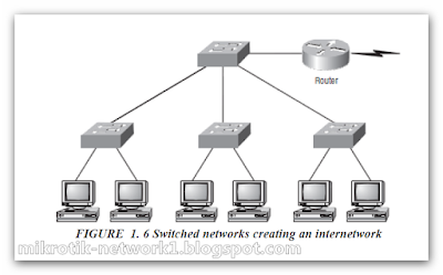
Once we have only switches in our network, things change a lot! Figure 1.6 shows the network that is typically found today.
switched network, you still need a router to provide your inter-VLAN communication, or internetworking.
Obviously, the best network is one that’s correctly configured to meet the business requirements of the company it serves. LAN switches with routers, correctly placed in the network, are the best network design.
Let’s go back to Figure 1.6. Looking at the figure, how many collision domains and broadcast domains are in this internetwork? Hopefully, you answered nine collision domains and three broadcast domains! The broadcast domains are definitely the easiest to see because only routers break up broadcast domains by default. And since there are three connections, that gives you three broadcast domains. But do you see the nine collision domains? Just in case that’s a no, I’ll explain. The all-hub network is one collision domain; the bridge network equals three collision domains. Add in the switch network of five collision domains—one for each switch port—and you’ve got a total of nine.
So now that you’ve gotten an introduction to internetworking and the various devices that live in an internetwork, it’s time to head into internetworking models.
Ccna Certified Mr.Mohamed Samir


0 comments:
Post a Comment